20FT Air Compressor Equipment Container
The 20ft Air Compressor Equipment Container is a modular all-in-one equipment unit that integrates a complete pneum...
Content
An energy storage container becomes a reliable, grid-ready asset when three systems operate in concert: the Battery Management System (BMS), the Energy Management System (EMS) and the Power Conversion System (PCS). Each has a distinct responsibility—cell-level safety and state estimation (BMS), system-level optimization and dispatch (EMS), and AC/DC conversion and protection (PCS)—but real-world performance depends on clear interfaces, coordinated control logic and fast, correct exchange of measurements, commands and alarms. This article explains how those pieces integrate, what data and commands flow between them, and practical engineering steps to achieve safe, efficient operation.
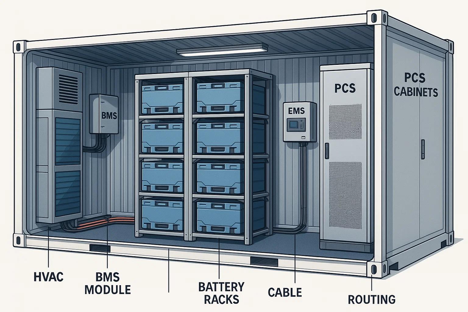
Start with precise definitions to avoid functional overlap and conflicting actions. The BMS protects cells and modules, manages balancing and reports cell-level parameters. The PCS executes power flows, enforces electrical protections and implements low-level control loops. The EMS makes higher-level decisions—scheduling charge/discharge, peak shaving, market participation and SOC management—based on site objectives and external signals. Documenting responsibilities reduces risk and clarifies which system takes priority in safety vs. operational conflicts.
Reliable data exchange is the backbone of coordinated action. Typical data flows include SOC, SOH and cell-level alarms from the BMS to EMS/PCS; real-time power setpoints and enable/disable commands from EMS to PCS; and instantaneous DC-link voltage and current from PCS to BMS/EMS for SOC reconciliation and safety checks. Choose robust protocols and define update rates and message priorities so time-sensitive protections are never delayed by non-critical telemetry.
|
Source |
Destination |
Typical payload |
Update rate |
|
BMS |
EMS, PCS |
Cell voltages, temps, SOC, balancing status, safety alarms |
100 ms–1 s (alarms faster) |
|
EMS |
PCS, site SCADA |
Power schedules, SOC targets, grid response commands |
1 s–1 min (depending on application) |
|
PCS |
BMS, EMS |
DC-link metrics, AC-side power, fault states, synchronization status |
50 ms–1 s (control signals fast) |
Define a control hierarchy that separates safety-critical actions from economic optimization. Safety interlocks from the BMS and PCS must supersede EMS commands. For example, if the BMS signals overtemperature, the PCS must immediately stop charging/discharging regardless of EMS dispatch. Use a deterministic arbitration strategy: explicit priority flags, heartbeat monitoring and watchdog timers to detect communication loss and move systems to a safe state automatically.
SOC estimation at the BMS level uses coulomb counting, voltage curves and temperature compensation. The EMS maintains an independent SOC estimate based on energy-in/out reported by PCS. Reconcile these estimates periodically: discrepancies indicate measurement drift, metrology errors or communication faults. Establish reconciliation windows and automatic correction procedures to keep trading or dispatch decisions aligned with the true usable capacity.
Thermal control is a combined responsibility. The BMS monitors cell temperatures and commands local balancing or limits charge/discharge currents. The EMS optimizes power schedules to avoid thermal excursions during peak ambient conditions. The PCS enforces current limits and can implement temporary derates. Cooperative logic—where EMS reduces charge power in response to aggregated BMS thermal warnings while PCS smoothly implements the reduction—prevents abrupt transitions that could create grid or mechanical stress.
Common field protocols include CAN, Modbus TCP/RTU, IEC 61850 and DNP3. Select protocols that satisfy latency, determinism and interoperability needs. Implement security layers: network segmentation, VPNs for remote access, certificate-based authentication and role-based access controls. Because safety depends on timely messages, design redundancy in physical links and use heartbeat messages so that loss-of-communication triggers a pre-defined safe behavior rather than leaving the system blind.
Thorough commissioning verifies not just individual subsystem functionality but integrated behavior. Test scenarios should include normal dispatch, transient responses, loss-of-communications, thermal excursions and simulated BMS faults. Validate arbitration rules, timeouts and safe-state transitions. Use staged tests: lab-level component validation, factory acceptance tests (FAT) with integrated EMS/PCS/BMS, then site acceptance tests (SAT) under realistic grid conditions.
Integration problems usually manifest as mismatched expectations: EMS commanding power outside BMS limits, delayed alarms, or inconsistent SOC values. Address issues by reviewing message schemas, timestamps and unit conventions; enabling verbose logging; and applying conservative operational limits while debugging. Maintain a single source-of-truth document describing signal definitions, units, accepted ranges and error codes to expedite troubleshooting.
Use the checklist below to validate that BMS, EMS and PCS will operate together predictably in the field. Completing each item reduces the chance of functional surprises during commissioning or operation.
Designing an energy storage container where BMS, EMS and PCS function as a coordinated system reduces risk and improves performance. Prioritize safety-first arbitration, robust communications, SOC reconciliation and rigorous commissioning. With these elements in place, operators can rely on consistent dispatch behavior, predictable degradation tracking and fast, safe responses to faults—transforming the container from a collection of components into a dependable grid asset.
If you share specifics about your system architecture (cell chemistry, nominal voltage, chosen protocols and primary use case such as frequency regulation or peak shaving), I can produce a tailored signal mapping table and an integration test plan for your project.


What to stay up to date?
Contact us via the email address below.
No. 178, Wuzhou East Road, Economic Development Zone, Yangzhou, Jiangsu.
Copyright 2024 Yangzhou Yichengke Integrated Technology Co., Ltd. All Rights Reserved.
![]()